If you’re interested in flow measuring devices, you’ve likely come across the Turbine Flow Meter. This common device is widely used in various industries to accurately measure volumetric flowrate. In this article, we will explore the inner workings of the Turbine Flow Meter, its components, and how it is calibrated.
Contents
How Does a Turbine Flow Meter Work?
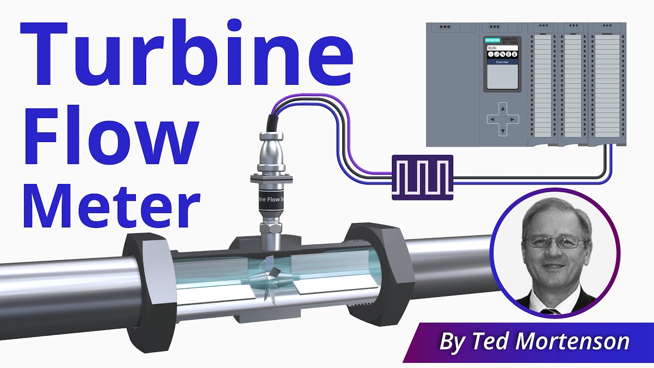
At its core, a Turbine Flow Meter consists of two major components: the mechanical part and the electrical part. The mechanical component includes a turbine rotor, usually made of stainless steel, placed in the flow path of a pipe. As the fluid flows through the pipe, it impinges on the rotor, causing it to spin. The rotational speed of the rotor is directly proportional to the flow velocity.
The electrical part of the Turbine Flow Meter is responsible for measuring the rotational speed of the rotor and converting it into electrical pulses. This is achieved using magnets attached to the rotor blades and a magnetic pickup sensor. As each rotor blade passes the pickup point, it generates an electrical pulse. The frequency of these pulses corresponds to the flow rate. The pickup sensing device can be a passive magnetic pickup or a more advanced active device like a Hall Effect sensor, which produces cleaner and more uniform square wave pulses.
Measuring Volumetric Flowrate with a Turbine Flow Meter
While the Turbine Flow Meter measures flow velocity, its primary purpose is to measure volumetric flowrate. Volumetric flowrate refers to the volume of fluid that passes a certain point in a unit period of time, typically expressed in units such as gallons per minute (GPM), cubic meters per second, or cubic feet per second.
To measure the volumetric flowrate accurately, each Turbine Flow Meter is assigned a unique K-Factor by the manufacturer. The K-Factor is the number of pulses generated for every unit of product passing through the meter. For example, a Turbine Flow Meter with a K-Factor of 3 pulses per gallon will generate 10 pulses per second at a volumetric flowrate of 200 GPM.
Calibrating a Turbine Flow Meter
When you purchase a Turbine Flow Meter, it comes with a calibration certificate or tag indicating its K-Factor. This allows you to accurately measure volumetric flowrate based on the generated pulses. To connect the Turbine Flow Meter to a control system, such as a PLC, you can use a frequency input card to read the pulse frequency and determine the flowrate.
During troubleshooting or loop calibration, a calibrator with a variable frequency output can be used to simulate the Turbine Flow Meter and validate its accuracy. This helps ensure that the meter is functioning correctly and providing accurate flow measurements.
Important Considerations and Industries
While Turbine Flow Meters are highly accurate and widely used, there are a few things to keep in mind. The K-Factor may not remain consistent across the entire flow rate measurement range, and these meters are not accurate at very low flow rates. Additionally, the viscosity of the fluid being measured can affect the rotor speed and meter calibration.
Despite these limitations, Turbine Flow Meters find applications in various industries. They are commonly used in oil and gas, water and wastewater, chemical, power, food and beverage, aerospace, pharmaceutical, and pulp and paper industries.
FAQs
Q: How does a Turbine Flow Meter work?
A: A Turbine Flow Meter consists of a mechanical rotor placed in the flow path of a pipe. As the fluid flows, it impels the rotor to spin, generating electrical pulses that correspond to flow velocity and volumetric flowrate.
Q: How is a Turbine Flow Meter calibrated?
A: Each Turbine Flow Meter is assigned a unique K-Factor by the manufacturer, which represents the number of pulses generated per unit of product passing through the meter. This K-Factor is used to accurately measure volumetric flowrate.
Conclusion
Turbine Flow Meters are essential devices for accurately measuring volumetric flowrate in various industries. The combination of a mechanical rotor and an electrical pickup allows for precise measurements based on the generated pulses. By understanding their operation and calibration, you can make better use of Turbine Flow Meters in your applications.
To learn more about Turbine Flow Meters and other related topics, visit Techal for comprehensive guides and insightful analysis.