Are you fascinated by the intricacies of running a 3-phase motor with a star-delta starter? In this article, we will delve into the details of defining the exact addresses for the devices in your system, allowing you to create a powerful and efficient PLC program. So let’s get started!

Understanding the Inputs and Outputs
Before we can begin writing the PLC program, it is essential to identify the inputs and outputs of the system or machine we are controlling. Looking at the diagram, we can see that our system has 2 inputs and 3 outputs. The inputs consist of the start and stop switches, while the outputs include the main, star, and delta contactors.
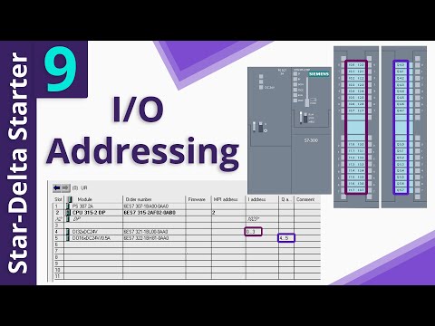
To gain a deeper understanding, let’s take a closer look at the input module’s details in the hardware. The “DI 32” module indicates that it has 32 digital inputs, allowing us to connect 32 different devices to this module. The addresses for this module start at byte 0 and continue to byte 3, providing a total of 4 bytes or 32 bits of memory space for addressing.
With this information, we can now determine the addresses for each input. Starting from byte 0, the address for the first input of this module would be “I 0.0”. Following the same pattern, the next input addresses would be “I 0.1”, “I 0.2”, and so on, until we reach the last input address, which is “I 3.7”. The “I” indicates that these addresses belong to the inputs, while the first digit represents the byte number and the second digit represents the bit number.
For our specific system, assuming the start switch is connected to the first input, the address we can use for this switch in the program is “I 0.0”. Similarly, if the stop switch is connected to the next input of the same module, its address would be “I 0.1”.
Now let’s move on to the output module. The “DO 16” module tells us that it has 16 digital outputs, allowing us to connect 16 different devices. The addresses for this module start at byte 4 and continue to byte 5, providing two bytes or sixteen bits for addressing.
Based on these addresses, the first output address for this module is “Q 4.0”, followed by “Q 4.1”, and so on, until we reach the last output address, which is “Q 5.7”. Assuming the main contactor is connected to the first output, the address we can use for this output in the software is “Q 4.0”. Similarly, the addresses for the star and delta contactors connected to the second and third outputs would be “Q 4.1” and “Q 4.2”, respectively.
FAQs
Q: What have I learned from this article?
By reading this article, you have gained insight into configuring the addresses for the devices in your system when creating a PLC program. You now understand how to determine the exact addresses for inputs and outputs, allowing you to control your system effectively.
Q: Can I implement this knowledge in my next PLC programming project?
Absolutely! Armed with this knowledge, you can confidently apply the concepts discussed in this article to your next PLC programming project. Understanding how to define addresses for devices is crucial in developing efficient and robust control systems.
Conclusion
In this article, we have explored the process of defining addresses for devices in a PLC program. By understanding the inputs and outputs of your system and configuring the appropriate addresses, you have the power to control your system efficiently and effectively.
Remember, Techal is here to empower you with knowledge about the ever-evolving world of technology. Stay tuned for more insightful articles like this. If you want to delve deeper into the world of technology, visit Techal for comprehensive guides and informative content. Let’s continue on this exciting technological journey together!