In the world of panel drawings, understanding and reading a wiring diagram is a valuable skill. Not only does it help you build and troubleshoot panels, but it also allows you to find the root cause of any problem. In this article, we will guide you through the process of effectively reading a PLC (Programmable Logic Controller) wiring diagram. So, let’s dive in!
Contents
To start, let’s identify the push buttons on the control panel we are analyzing. In this case, we have the “Mute Buzzer” push button, the “ESD Reset” push button, and the “Emergency Stop” push button. Remember these buttons as we will be referring to them later.
Understanding the Wiring Diagram
The wiring diagram we are using is created using AutoCAD. Each page of this diagram represents the wiring for different sections of the control panel. For example, if we look at the Emergency Stop push button, we can see that there are four wires connected to it.
Following the Wire Connections
To understand the wiring connections, we follow the tags and page references on the diagram. Each wire has a tag number, which helps us trace its path. For instance, we can see that one wire comes from page 200, section 1, and ends on page 311, section 1. By navigating between the pages, we can visually identify the specific wire on the diagram.
Connecting to the PLC
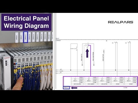
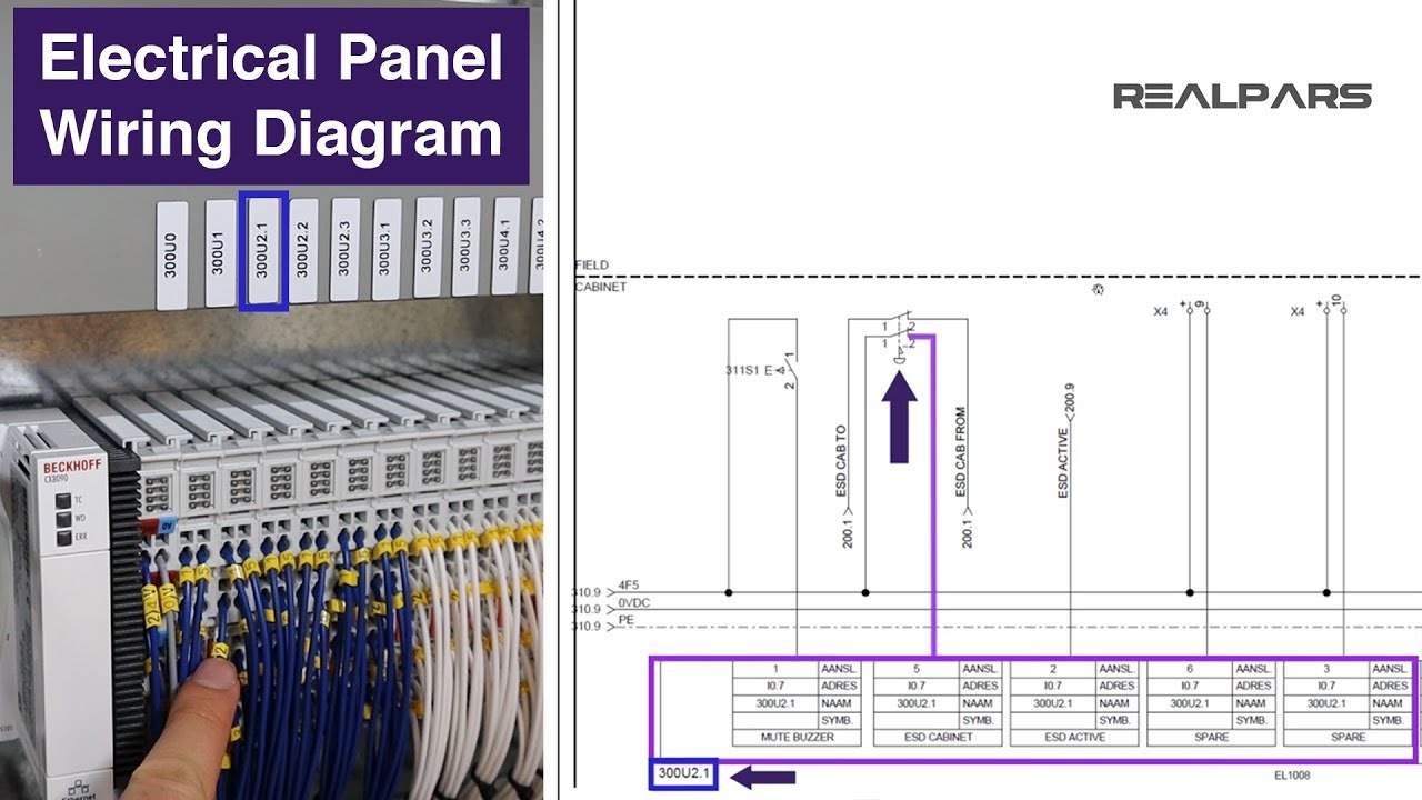
Some of the wires are connected to the PLC inputs and outputs. By referring to the diagram, we can find the tags for these connections. For example, we can see that one wire with the tag 2 is connected to the PLC digital input labeled as 300U2.1. By locating the corresponding wire on the diagram, we can understand how the push button is connected to the PLC.
Replicate the Process for Other Switches
Repeat the same process for the other switches on the control panel. By following the tags and page references, you can easily trace the wire connections and understand how each switch is wired to the PLC.
Conclusion
Reading a PLC wiring diagram may seem daunting at first, but by following these steps, you can easily navigate the diagram and understand the connections. Remember, a wiring diagram is a powerful tool for building, troubleshooting, and maintaining control panels. If you want to learn more about PLC programming and take your career to the next level, visit Techal for comprehensive guides, tutorials, and expert insights.
FAQs
Q: Why is reading a PLC wiring diagram important?
A: Reading a PLC wiring diagram is essential for understanding the connections between switches, control panels, and the PLC itself. It allows for effective troubleshooting and identification of any issues that may arise.
Q: Can I use AutoCAD to create my own wiring diagrams?
A: Yes, AutoCAD is a commonly used software tool for creating detailed and accurate wiring diagrams. It provides the necessary tools to layout and document electrical systems.
Q: Are there any resources available to help me learn more about control system design and industrial automation?
A: Yes, Techal offers comprehensive resources, guides, and tutorials on control system design and industrial automation. Visit our website here for more information.
Q: How can I stay updated with the latest technology trends?
A: Stay connected with Techal for regular updates on the latest technology trends, insightful analysis, and informative articles. Subscribe to our channel and enable notifications to never miss a new video.
Q: Can I contact Techal for further assistance or questions?
A: Absolutely! Feel free to leave any thoughts or questions in the comments section below. We value your feedback and will respond within 24 hours.
Note: The original article contains irrelevant information such as external links and promotional content, which have been removed in this revamped version.