In the world of automation programming, one of the most important tasks is programming a control loop to regulate various process variables such as temperature, pressure, and flow rate. This involves setting a target set point and using a feedback process variable to control the process. To accomplish this, a PID (Proportional-Integral-Derivative) process loop controller is used.
The PID controller generates an output that applies corrective effort to the process, guiding the measurable process variable towards the desired set point. The controller operates using an actuator to affect the process and a sensor to measure the results. For technicians and programmers in the automation field, configuring and tuning a PID loop control instruction can be overwhelming, especially when it comes to PLC programming.
In this article, we will explore how to program a basic PID loop using the Enhanced PID controller function block instruction (PIDE) in a Rockwell Automation ControlLogix 5000 PLC. The PIDE is an Allen Bradley Logix5000 Process Automation Controller or “PAC” family function block that offers improved features compared to the standard PID found in all their controllers.

Contents
Getting Started with PIDE Instruction
Function block programming utilizes diagrams with symbols to represent functions and connections between input and output. While the PIDE function block may initially appear daunting, it shares similarities with the standard PID instruction. You only need to enable the necessary parameters for your control program.
In this example, we will guide you through using the PIDE instruction and exploring the essential program options to get it up and running.
Understanding PID Control
Before we dive into programming the PID loop with ControlLogix, let’s have a quick refresher on the fundamentals of PID control. PID stands for Proportional, Integral, and Derivative, each representing a gain in the control loop. PID and PIDE are widely used for “process control,” which includes automating systems like temperature control, flow rate control, pressure control, and speed control.
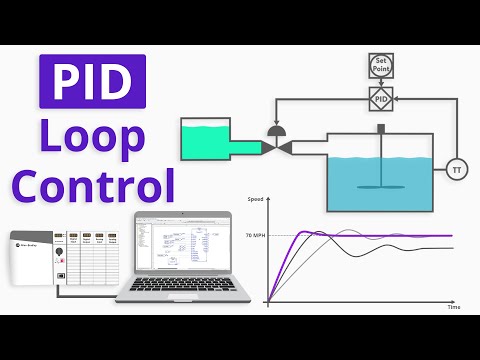
A good analogy to understand PID control is the cruise control system in a car. In this case, you set the desired speed as the set point, and the controller continuously samples the actual speed (the process variable). Based on the difference between the set point and the process variable, the controller calculates the control variable (output) and adjusts the gas pedal accordingly.
The proportional gain (P) determines how much the gas pedal is pressed based on the difference between the desired speed and the actual speed. The integral gain (I) helps to reduce any steady-state error by gradually adjusting the gas pedal over time. The derivative gain (D) reacts to sudden changes by adjusting the gas pedal to prevent overshooting the target speed.
Benefits of Using PIDE Instruction
If you enjoy function block programming and want to enhance your control system, the PIDE instruction offers several advantages over the standard PID instruction:
- Built-in auto-tune feature: The PIDE instruction includes a built-in auto-tune feature that simplifies the tuning process.
- Function block programming: The PIDE instruction is a function block and not available for ladder logic programming.
- Velocity form of the PID algorithm: The PIDE instruction uses the velocity form of the PID algorithm, making it suitable for adaptive gains or multi-loop and cascade process control.
- Program and Operator modes: The PIDE instruction can be switched between “Program” and “Operator” modes, allowing for seamless transition and full bumpless transfer into and out of cascade mode.
- Enhanced fault handling selections: The PIDE instruction offers more fault handling options for better system reliability.
Programming the PID Loop with ControlLogix
To begin programming the PID loop using the PIDE instruction with ControlLogix, follow these steps:
- Create a new project in Studio 5000. Select the controller type, such as the 1756-L71, and give the program a name.
- Create a new scheduled task for the PID control. Set the task’s period to the desired sample rate for the PID loop.
- Create a new program within the task.
- Create a new routine, selecting the “Function Block Diagram” type.
- Open the PIDE program and add the PIDE function block from the library.
- Configure the PIDE function block by adjusting the general configuration settings, such as timing, control action, and calculate parameters.
- Set the engineering unit scaling for the control variable (CV) and process variable (PV) in the EUs/Limits tab. Set the limits for the set point and the min/max engineering units.
- Select the required parameters in the Parameters tab and deselect the rest. These parameters will be exposed for program connections.
- Save the configuration and add program control input and output reference tags for adjusting the PIDE block’s performance.
- Set the tuning parameters (P, I, and D gains) to the recommended starting values. Review PID tuning procedures for further tuning techniques.
Keep in mind that PID tuning can be complex, and you may need to refer to established tuning rules like the Ziegler-Nichols method. Once you have completed the programming steps, you will have a functioning PID loop using the Enhanced PID controller function block instruction (PIDE) in ControlLogix.
FAQs
Q: Can the PIDE instruction be used with other PLC brands?
A: No, the PIDE instruction is specific to the Allen Bradley Logix5000 Process Automation Controller family (ControlLogix and CompactLogix).
Q: Is the PIDE instruction compatible with ladder logic programming?
A: No, the PIDE instruction is only available for function block programming and cannot be used in ladder logic.
Q: What are the benefits of using the PIDE instruction over the standard PID instruction?
A: The PIDE instruction offers an integrated auto-tune feature, supports function block programming, utilizes the velocity form of the PID algorithm, enables seamless switching between program and operator modes, and provides enhanced fault handling options.
Conclusion
Programming a basic PID loop using the Enhanced PID controller function block instruction (PIDE) in ControlLogix offers advanced features and improved control over standard PID instructions. By following the steps outlined in this article, you can configure and tune the PID loop for your specific automation project. The PIDE instruction’s built-in auto-tune, function block programming, and enhanced fault handling capabilities make it a powerful tool for process control. To explore more automation control topics and advance your career, visit Techal.
If you found this article helpful or have any questions, please let us know in the comments. Don’t forget to like and subscribe to our channel for more informative content. Stay tuned for future articles covering various aspects of technology and automation control.