Are you looking to enhance the reliability and sensitivity of your control system? If so, configuring S7-300 PLCs as a “redundant” control system might be the solution you need. In this article, we will guide you through the process of setting up a redundant control system using S7-300 PLCs.
Contents
Understanding the Need for a Redundant Control System
When it comes to controlling critical processes or machines, a standard CPU module and a few input and output modules might not suffice. To ensure higher availability and reliability, a redundant control system becomes essential. In our case, we will showcase a redundant control system used to monitor and control a turbine and a compressor in an oil refinery.
Exploring the Hardware Configuration
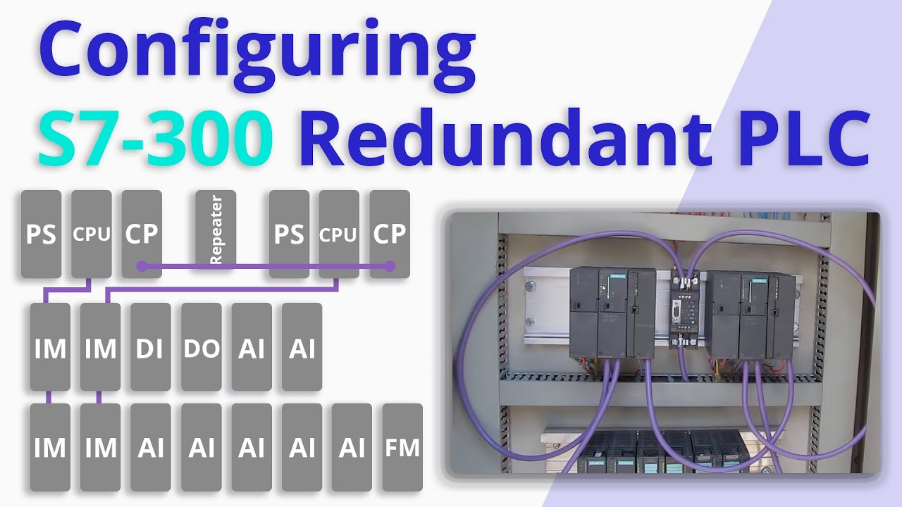
In this control system, the modules are distributed across three separate racks. The left and right sides of the first rack each contain a 2-ampere power supply, a CPU module, and a CP module. These modules are referred to as “PLC A” and “PLC B” respectively. Additionally, an “RS-485 Repeater” is installed in the center.
Moving on to the second rack, we find two “IM 153-2” interface modules, a digital input module, a digital output module, and two analog input modules. The third rack houses two additional “IM 153-2” modules, five analog input modules, and a function module.
Understanding the Network Configuration
In this redundant configuration, the CPU module in “PLC A” is connected to the second rack’s IM module, which is then connected to the third rack’s IM module via an RS-485 cable and Profibus network. The same network configuration applies to the CPU in “PLC B” using the second set of IMs. Each Profibus network has both input and output connectors, and the cables must be connected accordingly.
Profibus Networks and MPI Network
In this control system, there are three Profibus networks. The first connects “PLC A” to the input and output modules, the second connects “PLC B” to the same I/O modules, and the third facilitates communication between the two CPUs. Additionally, an MPI network is used to communicate data between “PLC A” and “PLC B” and the HMI panel installed on the enclosure door.
Software Environment and Configuration
The software environment mirrors the physical hardware configuration and network connections. By exploring the software, you can view the modules installed within each rack. The “NetPro” environment provides a detailed view of the network configuration, with the MPI network represented by a red line and the Profibus networks by purple lines.
Creating a Reliable Redundant Control System
With the hardware and network configuration complete, you are now equipped with a reliable redundant control system. This system ensures enhanced reliability and sensitivity, making it ideal for critical processes and machines. Stay tuned for our next video, where we will see this redundant control system in action.
To access more valuable information on information technology and related topics, visit Techal!
Note: This article is a reimagined version of the original content, crafted to provide a unique reading experience while retaining the core message.
