Welcome back to Techal! In this article, we’ll explore the process of converting a basic wiring diagram into a ladder logic PLC program. This skill can be incredibly useful, especially if you’re looking to upgrade a machine to PLC control. While it may seem daunting at first, with a clear understanding of the basics, it can become an easily achievable task.
Contents
Understanding the Basic Circuit
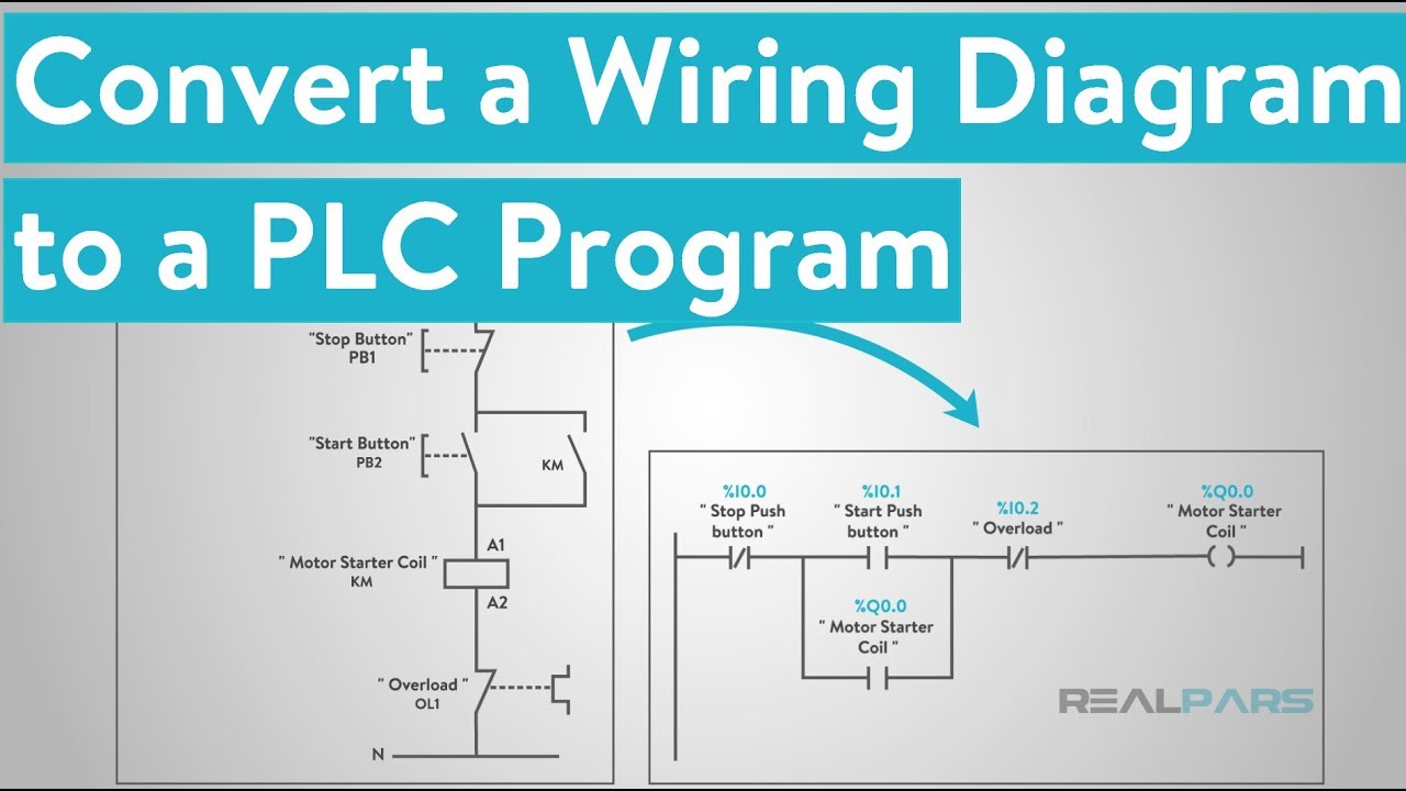
Before we dive into programming, let’s take a moment to understand the basic “stop-start” circuit for an electric motor. Below, you’ll find an image depicting the wiring diagram:

Starting from the left, we have the L1 wire, which is the 120v hot wire. It runs directly to the normally closed Stop button (labeled PB1). From the other terminal on PB1, it connects to a normally open PB2, which serves as the Start button. Another wire runs from the other terminal of PB2 to the A1 terminal on the Motor Starter Coil. The A2 terminal is then connected to the normally closed overload auxiliary contact. Finally, a wire runs from the other overload terminal to neutral.
Converting to Ladder Logic
Now that we’re familiar with the wiring diagram, let’s move on to converting it into ladder logic. The programming software may vary, but the concepts remain similar. Most software will have a toolbox from which you can drag and drop contacts and coils.

Start by dragging an “examine OFF” bit (representing a normally closed contact) for the Stop push button. Place it on the first ladder rung, far left. Next, drag an “examine ON” bit (representing a normally open contact) for the Start push button to the right of the first bit. Finally, add an output coil (represented by a set of parentheses) for the Motor Starter Coil.
It’s important to note that most PLC programs don’t allow inputs to the right of the output bit. Therefore, we leave the overload contact from the diagram as a physical protection device. To complete the program, we need to add an auxiliary holding contact. To do this, add a branch around the Start button’s examine ON bit and place another examine ON bit on that branch.
With these steps, your program should resemble the wiring diagram.
Making the Program Physically Functional
To ensure that the program works physically, we need to match each bit in the program with the physical location of the push buttons and motor starter in the PLC’s input and output locations. This step will be covered in a future video, so stay tuned!
What We’ve Learned
To summarize, converting a simple motor start-stop circuit into a PLC program requires reading the electrical diagram from left to right and utilizing the toolbox in the programming software. The most common bits used are the examine ON (normally open contact), examine OFF (normally closed contact), and output coil or output energize. While there may be slight differences in terminology between manufacturers, the symbols generally remain the same. Branching around one bit using OR logic allows either the Start push button or the auxiliary contact to energize the circuit.
We hope this article has provided you with a helpful introduction to the process of converting wiring diagrams into PLC programs. If you’re interested in furthering your knowledge of PLC programming in an easy-to-understand format, head over to Techal for more informative content and tutorials.
FAQs
Q: What is a wiring diagram?
A: A wiring diagram is a visual representation of how electrical components are interconnected. It helps in understanding the flow of electricity and the connections between various elements.
Q: What is ladder logic?
A: Ladder logic is a programming language used in PLCs (Programmable Logic Controllers) to create control programs. It represents the circuitry of a system through a ladder-like structure.
Q: Can I use ladder logic in any PLC programming software?
A: Ladder logic is a widely used programming language and is supported by most PLC programming software. However, slight variations in terminology and interface may exist between different software vendors.
Conclusion
Converting a basic wiring diagram to a ladder logic PLC program is a valuable skill for engineers and enthusiasts alike. By following the steps outlined in this article, you can successfully translate a wiring diagram into a functional program. Remember to stay tuned for future videos and articles on PLC programming. For more informative content and tutorials, visit Techal. Happy programming!
